
EA Carts guide
How to Wire Lights on a 48 Volt Golf Cart Like a Pro
Specifications, pricing, programs and road-use rules can change. Confirm current product details with EA Carts and check state and local requirements before purchasing or driving on public roads.
EA Carts lists LED lights and turn signals as standard on its EA4R+, EA4F+, EA6R+ and EA4x4 models. This wiring guide applies to all 48 volt golf cart brands including Club Car, E-Z-GO, and Yamaha.
Learning how to wire lights on a 48 volt golf cart is one of the best upgrades you can make, whether you want to cruise after sunset, meet street-legal requirements, or just make your ride look incredible with LED underglow. But here is the problem most cart owners run into: 48 volts is far more than a 12-volt-only light is built for. Send full battery voltage through one and it can burn out in seconds.
I have wired lights on dozens of 48 volt golf carts, Club Car, the aluminum-frame golf cart brand owned by Platinum Equity, Precedents, EZGO RXVs, Yamaha, the Japanese motor company known for engine reliability, Drives, and our own EA Carts models. After blowing a few fuses (and one very expensive LED light bar) early on, I learned exactly what works. This guide walks you through every step: choosing the right voltage reducer, selecting the correct wire gauge, installing headlights and taillights, wiring turn signals, and adding underbody LEDs. No electrical engineering degree required.
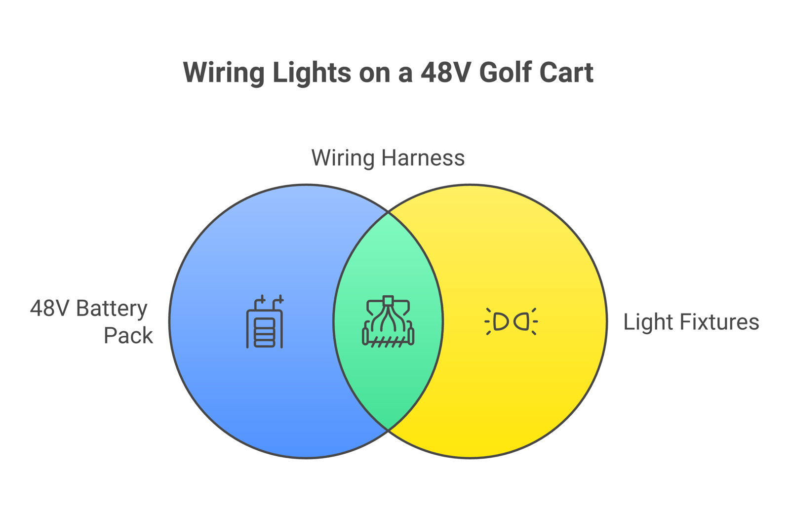
Understanding Your 48 Volt Battery Configuration
Before you touch a single wire, you need to know what battery setup your golf cart's batteries use and the voltage range of the system. This determines everything about how you wire lights on your cart, and whether you need a voltage reducer at all.
Four 12-Volt Batteries (Series Configuration)
If your 48 volt cart runs on four 12-volt batteries wired in series, you are in luck. You can tap a single 12-volt battery directly to power your lights without any voltage reducer. The positive terminal of that one battery provides 12 volts, which is exactly what LED headlights, taillights, and accessories need.
How it works: Four batteries are connected positive-to-negative in a chain. Battery 1 positive (12V) connects to Battery 2 negative. Battery 2 positive (24V) connects to Battery 3 negative. And so on until you reach 48V total. To get 12 volts for your lights, connect to the positive and negative terminals of just one battery in the chain.
Six 8-Volt Batteries (Series Configuration)
Here is where things get tricky. With six 8-volt batteries, you cannot get a clean 12-volt tap. One battery gives you only 8 volts, below what a 12-volt light is built for. Two batteries give you 16 volts, more than a 12-volt light is rated for unless its data sheet lists a wider input range.
You absolutely need a voltage reducer (also called a voltage converter or DC-DC converter) for this setup. The reducer takes the full 48-volt input and steps it down to a stable 12-volt output. Non-negotiable.
Eight 6-Volt Batteries (Less Common)
Some older 48 volt carts use eight 6-volt batteries. The same rule applies, two batteries give you 12 volts, but tapping just two puts uneven load on the pack. A voltage reducer is still the recommended approach for longevity and consistent performance.
Tools and Materials You Need
Gather everything before you start. Nothing kills momentum like a trip to the hardware store mid-install.
Required Tools
- Wire strippers, for preparing connections
- Wire crimpers, for attaching ring terminals and spade connectors
- Digital multimeter, absolutely essential for verifying voltage at every connection point
- Electric drill with 7/16" and 9/16" bits, for mounting headlights and taillights
- Screwdriver set (Phillips and flathead)
- Socket set (10mm and 13mm are most common on golf carts)
- T30 and T15 Torx bits
- Wire cutters
- Heat gun (for heat-shrink tubing)
- Marking pencil
- Measuring tape
- Zip ties (25+ count)
Required Materials
- Voltage reducer (48V-to-12V, rated for your total accessory load, more on sizing below)
- LED headlight and taillight kit
- 18 AWG primary wire (for light runs, red and black, minimum 25 feet each)
- 14 AWG wire (for higher-draw accessories or longer runs)
- Ring terminals (assorted sizes)
- Spade connectors
- Inline fuse holder with 15-amp ATC fuse
- Rubber grommets (for protecting wires through drilled holes)
- Heat-shrink tubing
- Electrical tape (3M Super 33+ or equivalent)
- Wire loom or split tubing (for protecting harness runs)
- Mounting hardware (screws, double-sided tape for voltage reducer)
How to Choose the Right Voltage Reducer
This is where most DIY installers go wrong. They grab the cheapest voltage reducer they can find and wonder why their lights flicker or the reducer overheats. Here is how to size it correctly.
Calculate Your Total Amperage Draw
Add up every 12-volt accessory you plan to run simultaneously:
| Accessory | How to Find the Draw |
|---|---|
| LED headlights (pair) | Rated watts divided by 12 (24 W is 2 A) |
| LED taillights (pair) | Rated watts divided by 12 |
| Turn signals (all four) | Only while flashing; check the lamp rating |
| Brake lights | Only while braking; check the lamp rating |
| LED underbody kit | Depends on strip length; check the kit |
| Horn | Short bursts; check the horn rating |
| Radio/speakers | Rises with volume; check the unit's rating |
| USB charger | Check the charger's rated output |
Add the rated amps of everything that can run at the same time. Watts convert to amps at 12 volts by dividing by 12, so a 60-watt load is 5 amps. Add LED underbody lights, a sound system, and a horn, and the total climbs quickly.
Voltage Reducer Sizing Guide
| Reducer Rating | Best For | Max Continuous Load |
|---|---|---|
| 10-amp | Headlights and taillights only | 120 watts |
| 20-amp | Full light kit + turn signals + horn | 240 watts |
| 30-amp | Everything above + radio + speakers + accessories | 360 watts |
My recommendation: Buy one size up from what you think you need. A 20-amp reducer costs a little more than a 10-amp, and it gives you headroom for future upgrades.
Important note for 30-amp reducers: Some voltage reducers, often the higher-amp units, have a third switched-input wire that must be connected to the key switch hot wire. This wire turns the reducer on and off with the key, preventing battery drain when the cart is parked. Check your reducer's instructions to see whether yours has one.
Step 1: Safety First, Disconnect the Battery Pack
I cannot stress this enough: 48 volts can deliver a serious shock. The shock risk is lower than at household voltage, but a battery pack can still cause burns, arc flash, and damage to your cart's controller.
Pre-Work Safety Checklist
- Turn the key switch to the OFF position
- Flip the cart into TOW/MAINTENANCE mode (this disconnects the motor controller)
- Disconnect the main negative battery cable first, then the main positive cable
- Secure disconnected cables away from battery terminals with zip ties or tape, a loose cable touching a terminal restarts the circuit
- Remove any jewelry, watches, or metal bracelets (metal conducts electricity across terminals)
- Wear safety glasses, batteries can spark when connections are made or broken
- Work in a well-ventilated area if using lead-acid batteries (hydrogen gas buildup is a real hazard)
For related electrical safety information, consult the NHTSA vehicle lighting standards and your cart manufacturer's service manual.
Step 2: Mount and Wire the Voltage Reducer
If your cart has four 12-volt batteries, you can skip this step and connect directly to a single battery (jump to Step 3). For six 8-volt or eight 6-volt setups, follow this carefully.
Mounting the Reducer
Find a flat metal surface under the seat or in the battery compartment. Voltage reducers generate significant heat during operation, mounting on metal helps dissipate that heat. Never mount on plastic; it can warp or melt.
- Secure with screws (preferred) or heavy-duty double-sided tape
- Keep at least 2 inches away from battery terminals
- Ensure the reducer is protected from rain and tire spray
- Leave clearance for air circulation around all sides
Wiring the Input Side (48V In)
The input side of the reducer connects to your full 48-volt battery pack:
- Identify the first battery in series. This is the battery with a positive terminal that is NOT connected to another battery. It feeds into the system.
- Identify the last battery in series. This battery has a negative terminal with a wire running to the cart's controller or motor.
- Connect the reducer's positive INPUT wire (usually red) to the positive terminal of the FIRST battery
- Connect the reducer's negative INPUT wire (usually black) to the negative terminal of the LAST battery
- Install a 15-amp inline fuse on the positive input wire, within 6 inches of the battery terminal. This protects against short circuits
Critical: Strip approximately 0.25 inches of insulation from each wire. Use ring terminals crimped securely, then tighten onto the battery terminal bolts. A loose connection creates resistance, which creates heat, which starts fires.
Testing the Reducer Output
Before connecting any lights:
- Reconnect your main battery cables temporarily
- Switch the cart to RUN mode
- Turn the key to ON (required for 30-amp reducers)
- Touch your multimeter probes to the reducer's OUTPUT terminals
- Reading should be close to 12 volts DC; the reducer's data sheet gives its exact output range
If you see 0 volts, check your input connections. If you see well above the reducer's rated output, something is wired incorrectly, disconnect immediately and recheck polarity.
Disconnect the batteries again before proceeding to light installation.
Step 3: Install Headlights
Most aftermarket golf cart headlight kits come with a paper template for marking cut locations on the front cowl.
Mounting Process
- Position the template on the cart's front body panel. Align it using existing body lines or screw holes as reference points.
- Mark the cut lines with a marking pencil. Double-check measurements. You cannot un-cut fiberglass or ABS plastic.
- Drill pilot holes at the corners of the cutout area
- Cut the opening using a jigsaw with a fine-tooth blade or a rotary tool. Go slow to prevent cracking.
- Install rubber grommets in every hole where wires pass through body panels. This prevents chafing that leads to short circuits over time.
- Seat the headlight assemblies into the cutouts and secure with the provided mounting hardware.
- Do NOT fully tighten mounting bolts until you have run all wiring and confirmed alignment.
Headlight Wiring
LED headlights have two wires: positive (red or white) and negative (black or green).
- Run the positive wire from each headlight back to the light switch location (usually the dash area)
- Run the negative wire to a common ground point or back to the reducer's negative output
- Use 18 AWG wire minimum for standard LED headlights (under 4 amps per pair)
- Use 16 AWG wire if running halogen bulbs or high-output LED bars that draw more than 4 amps
- Secure all wiring along the frame with zip ties every 12-18 inches. But do not cinch them tight yet until all wiring is complete
Step 4: Install Taillights and Brake Lights
Taillights typically mount on the rear body panel or bumper. Many kits combine taillights, brake lights, and turn signals into a single assembly.
Mounting
- Use the provided template (or measure and mark) the mounting location on the rear cowl
- Drill mounting holes and install rubber grommets
- Feed wires through the grommets before seating the light assembly
- Secure with mounting screws
Taillight Wiring (3-Wire System)
Most combination tail/brake light assemblies use three wires:
- Black wire, Ground (connect to common ground)
- Brown or red wire, Running taillights (always on when key is turned)
- Green or yellow wire, Brake light circuit (activates when brake pedal is pressed)
For the brake light circuit, you need to tap into the brake switch. On most golf carts, the brake switch is a small microswitch located near the brake pedal assembly under the dash. One wire from the switch goes to your brake light wire, providing power only when the pedal is pressed.
Step 5: Wire Turn Signals (For Street Legal Compliance)
If you want your cart to be street legal, turn signals are required equipment on a low-speed vehicle under federal rules. Carts like the EA4R+ 60V come with turn signals pre-installed, but if you are retrofitting an older cart, here is how.
Turn Signal Components
- Turn signal switch (column-mounted or dash-mounted)
- Flasher relay (electronic LED-compatible type, standard thermal flashers cause hyper-flash with LEDs)
- Front turn signal lights (amber)
- Rear turn signal lights (amber or red, depending on local regulations)
Turn Signal Wiring Diagram (Text Description)
The turn signal circuit consists of four main connections flowing from the flasher relay through the turn signal switch to the individual lights:
- Power feed: 12V positive from the voltage reducer output (or battery tap) connects to the flasher relay input terminal (usually marked "B" or "+")
- Flasher output: The flasher relay output terminal (marked "L") connects to the turn signal switch common input
- Left circuit: The turn signal switch "left" output connects to both the front-left and rear-left turn signal lights (wired in parallel)
- Right circuit: The turn signal switch "right" output connects to both the front-right and rear-right turn signal lights (wired in parallel)
- All ground wires from all four turn signal lights connect to a common ground
Wire gauge: Use the gauge your turn signal kit specifies, in automotive primary wire for durability and heat resistance.
Install a 10-amp fuse on the positive feed wire between the power source and the flasher relay.
Hazard Lights
Some turn signal switch assemblies include a hazard button that activates all four turn signals simultaneously. If yours does not, you can add a separate DPDT (double-pole, double-throw) toggle switch that bypasses the turn signal switch and connects both left and right circuits to the flasher simultaneously.
Step 6: Add Underbody LED Lights
Underbody LEDs are purely cosmetic, but they look notable on a blacked-out golf cart rolling through the neighborhood at dusk. EA Carts, the electric golf cart manufacturer based in Carmel, Indiana, offers a purpose-built LED Underlight kit designed specifically for golf carts.
Underbody LED Installation
- Plan your layout: Most kits include 4 LED strips, two longer strips for the sides and two shorter strips for front and rear. Measure your cart's frame to determine strip placement. Keep strips tucked up under the frame rail so they illuminate the ground without being directly visible.
- Clean mounting surfaces: Use isopropyl alcohol to remove dirt, grease, and debris from the frame where strips will mount. The adhesive backing on LED strips fails quickly on dirty surfaces.
- Mount the strips: Peel the adhesive backing and press firmly along the frame rail. For extra security (and I strongly recommend this), add zip ties every 8-10 inches. Adhesive alone can let go from vibration.
- Run the wiring: Route all LED strip leads to a central junction point under the seat or near the battery compartment. Use wire loom to protect runs from road debris.
- Connect to power: Wire the LED controller (if your kit includes one) to the 12V output of your voltage reducer. Use an inline switch or remote control to toggle the LEDs independently from your headlights.
- Fuse the circuit: Install a 5-amp inline fuse on the positive feed to the LED strips.
LED Color and Legality
Check your local and state regulations before choosing colors. In many jurisdictions:
- Blue and red underbody lights are restricted in many states because they are used by emergency vehicles
- White and amber are allowed in more places, but check your state
- Green, purple, and other colors vary by state
- Underbody lights may need to be turned off on public roads in some areas
For a full breakdown of what you need for legal road use, check our complete street-legal golf cart guide.
Step 7: Wire the Master Light Switch
All your lights should route through a master switch mounted on the dash. This keeps things organized and lets you turn everything on or off with a single action.
Switch Wiring Layout
For a basic headlight/taillight setup with a single on-off toggle switch:
- 12V positive from voltage reducer output, fuse (15-amp), switch input terminal
- Switch output terminal, splits to headlight positive and taillight positive (wired in parallel)
- All negative/ground wires, common ground bus or direct to reducer negative output
For a more advanced multi-switch setup, use a fuse block:
- 12V positive from reducer, main fuse (20-amp), fuse block input
- Fuse block output 1 (10A fuse), headlight switch, headlights
- Fuse block output 2 (10A fuse), taillight/brake circuit
- Fuse block output 3 (10A fuse), turn signal circuit
- Fuse block output 4 (5A fuse), underbody LED switch, LEDs
- Fuse block output 5 (10A fuse), accessory circuit (radio, USB, etc.)
A fuse block makes future upgrades dramatically easier. You just add another fused circuit instead of splicing into existing wires.
Step 8: Final Connections and Testing
With all lights mounted and wired, it is time to bring everything online.
Connection Checklist
- Inspect every connection. Tug each wire gently at every terminal. If it pulls out, re-crimp it.
- Check for bare wire exposure. Any exposed copper should be covered with heat-shrink tubing or electrical tape.
- Verify polarity. Double-check that every positive wire connects to positive, and every negative connects to negative. Reversed polarity will blow LEDs instantly.
- Tighten all ring terminals on battery and reducer connections.
- Reconnect the main battery cables, positive first, then negative.
- Switch the cart to RUN mode and turn the key ON.
Testing Sequence
- Multimeter check: Verify 12V at the reducer output (or battery tap)
- Headlights: Turn on the master switch. Both headlights should illuminate evenly.
- Taillights: Confirm both taillights glow with the master switch on.
- Brake lights: Have someone press the brake pedal while you watch the rear. Brake lights should be noticeably brighter than running taillights.
- Left turn signal: Activate and confirm front-left and rear-left blink in sync.
- Right turn signal: Same check for the right side.
- Hazard lights: All four turn signals blink simultaneously.
- Underbody LEDs: Toggle on and verify all strips illuminate.
- Drive test: Take the cart for a slow lap. Check for flickering (indicates a loose connection), listen for buzzing from the reducer (normal at low levels, concerning if loud), and verify lights stay on over bumps.
Wire Gauge Quick Reference Chart
Choosing the right wire gauge limits voltage drop and heat. Each row is sized for the current shown, and each gauge keeps voltage drop under 10 percent at the top of that current and run length, counting the wire out and back, using copper resistance from the NBS Copper Wire Tables (Handbook 100) at 25 °C. For a tighter 3 percent target on headlights, go one or two sizes thicker:
| Application | Current Draw | Wire Run < 10 ft | Wire Run 10-20 ft |
|---|---|---|---|
| LED headlights | 2-4A | 18 AWG | 16 AWG |
| LED taillights | 1-2A | 18 AWG | 18 AWG |
| Turn signals | 2-3A | 18 AWG | 16 AWG |
| Underbody LEDs | 2-4A | 18 AWG | 16 AWG |
| Light bar (high-output) | 5-15A | 14 AWG | 12 AWG |
| Full accessory run (combined) | 15-20A | 12 AWG | 10 AWG |
| Voltage reducer input leads | 5-10A | 14 AWG | 12 AWG |
Rule of thumb: When in doubt, go one gauge thicker. 16 AWG copper has 4.10 ohms per 1,000 feet against 6.51 for 18 AWG, about 37 percent less resistance. For example, 4 amps over a 10-foot run is 20 feet of wire out and back: 4 x 6.51 x 20 / 1,000 = 0.52 volts on 18 AWG, about 4.3 percent of 12 volts, and 0.33 volts (2.7 percent) on 16 AWG.
Fuse Sizing Guide
Every circuit needs a fuse. Period. An inexpensive fuse protects your lights and wiring, and more importantly, prevents electrical fires.
| Circuit | Recommended Fuse | Fuse Type |
|---|---|---|
| Headlight circuit | 10A | ATC blade fuse |
| Taillight/brake circuit | 10A | ATC blade fuse |
| Turn signal circuit | 10A | ATC blade fuse |
| Underbody LED circuit | 5A | ATC blade fuse |
| Voltage reducer input | 15A | ATC blade fuse |
| Main accessory feed | 20-30A | ATC/Maxi blade fuse |
| Radio/audio circuit | 10A | ATC blade fuse |
Sizing rule: A common rule of thumb is to rate the fuse at 125 percent of the circuit's maximum expected draw, so a circuit that draws 8 amps gets 8 x 1.25 = 10 amps. The fuse protects the wire, so never use one rated higher than the wire can carry. A fuse far above the circuit draw defeats the purpose.
Troubleshooting Common Issues
Even experienced installers run into problems. Here are the issues I see most often and how to fix them.
Lights Flicker While Driving
- Cause: Loose connection at a terminal, ring terminal, or splice
- Fix: Inspect every connection point. Re-crimp or solder any suspect joints. Add heat-shrink tubing to prevent future loosening from vibration.
Headlights Dim When Brakes Are Applied
- Cause: Insufficient ground wire gauge or shared ground connection that cannot handle combined load
- Fix: Run a dedicated 14 AWG ground wire from the light circuits directly to the voltage reducer negative output terminal (or battery negative). Do not daisy-chain grounds through the cart frame.
Turn Signals Hyper-Flash (Blink Too Fast)
- Cause: Using a thermal flasher relay with LED bulbs. LED bulbs draw far less current than incandescent, so the thermal flasher thinks a bulb is burned out.
- Fix: Replace with an electronic LED-compatible flasher relay. These flash at a fixed rate regardless of load.
Voltage Reducer Gets Extremely Hot
- Cause: Overloaded (drawing more amps than the reducer is rated for), poor ventilation, or mounted on plastic
- Fix: Calculate your total draw (see the table above). If it exceeds the reducer rating, upgrade to a higher-amp unit. Ensure the reducer is mounted on metal with clearance for airflow.
Lights Work But Drain Batteries Overnight
- Cause: No key-switch connection on the voltage reducer. The reducer stays active even when the cart is off, slowly draining the battery pack.
- Fix: Wire the reducer through the key switch (if your reducer has a switched-input wire). Or install a manual disconnect switch on the reducer's positive input wire.
No Power at Output Despite Correct Wiring
- Cause: Blown fuse, dead reducer, or cart not in RUN mode
- Fix: Check the inline fuse first (the quickest check). Verify the cart is in RUN mode with key ON. Test the reducer's input voltage. You should see ~48V. If input is good but output is 0V, the reducer is likely faulty.
Wiring Best Practices That Prevent Problems
After wiring lights on more golf carts than I can count, these are the habits that separate clean, reliable installations from the ones that come back with problems:
- Solder and heat-shrink critical joints. Crimp connectors are fine for most connections, but anywhere that sees heavy vibration (near the motor, axle, or suspension) deserves a soldered joint with heat-shrink tubing.
- Never run wires near hot exhaust components on gas carts. Electric carts like the EA4R+ 60V do not have this issue, but it matters if you are working on a gas-powered model.
- Use split wire loom on every run longer than 12 inches. It protects against abrasion, UV damage, and rodent chewing (surprisingly common in golf cart garages).
- Label every wire at both ends with a label maker or tape flag. When something needs service in two years, you will thank yourself.
- Keep wire runs as short as possible. Longer runs increase voltage drop and the chance of damage. Route directly along frame members rather than taking scenic paths through the cart body.
- Always use rubber grommets where wires pass through sheet metal or fiberglass. A single sharp edge can wear through insulation in weeks of driving, causing a short circuit.
- Test as you go. Connect and test each circuit individually before moving to the next. It is far easier to troubleshoot one circuit at a time than to debug six circuits wired at once.
- Photograph your wiring before closing panels. A quick phone photo of the wiring layout behind the dash saves hours of troubleshooting later.
Which EA Carts Models Come Pre-Wired for Lights?
If this guide is making you rethink the DIY approach, I get it. Wiring a full light kit is roughly a 3 to 5 hour job for many owners and requires some The good news: several EA Carts models come with lighting already integrated from the factory.
| Model | Voltage | Included Lighting | Additional Options |
|---|---|---|---|
| EA4F+ 60V | 60V | LED headlights, taillights and turn signals | Custom color options |
| EA4R+ 60V | 60V | Full LED kit with turn signals standard | LSV-ready equipment |
Browse the full lineup in our complete cart collection, or check out golf cart accessories for add-on lighting kits.
How 48 Volt Wiring Differs from 36 Volt Systems
If you have read guides for 36V vs 48V golf carts, you know the voltage difference changes a few key things:
- Voltage reducer compatibility: Verify your reducer is rated for 48V input (not just 36V). Running a reducer above its rated input voltage can damage it, so match the input range on its label.
- Battery tap options: 36V carts with six 6-volt batteries can tap two batteries for exactly 12V. 48V carts with six 8-volt batteries cannot get a clean 12V tap, hence the reducer requirement.
- Available power: 48V systems deliver more power, which means the cart motor puts more electrical noise on the system. If you hear buzzing through your speakers or see slight LED flicker, add a 12V inline noise filter between the reducer output and your accessories.
- Range impact: Running lights off a 48V system has minimal impact on your electric golf cart range. A pair of LED headlights drawing 3 amps at 12V uses 3 x 12 = 36 watts, which is 36 / 48 = 0.75 amps at 48V before converter losses. On a cart with a 100Ah battery pack, that is 0.75 percent of the pack per hour of driving.
Frequently Asked Questions
Can I wire 12V lights directly to a 48V golf cart without a voltage reducer?
No. Connecting 12V-only lights directly to a 48V battery pack can destroy the lights and can melt wiring or cause a fire. You must either use a voltage reducer to step down to 12V, or tap a single 12V battery if your cart uses four 12V batteries in series. There is no safe shortcut here.
How much does a voltage reducer cost?
A quality 48V-to-12V voltage reducer costs more as the amperage rating goes up. Do not buy the cheapest no-name units. They tend to overheat and fail quickly. Stick with established golf cart accessory brands.
Will adding lights affect my golf cart's speed or performance?
The electrical draw from LED lights is negligible. If a full LED lighting package (headlights, taillights, turn signals, and underbody LEDs) draws 10 to 15 amps at 12V, that is 10 x 12 / 48 = 2.5 to 15 x 12 / 48 = 3.75 amps at 48V. That is a tiny fraction of what the drive system handles; EA's EA4x4, for example, lists a 72V/200A system. You will not notice any difference in speed or performance.
Do I need to add lights to make my golf cart street legal?
Yes. According to NHTSA Federal Motor Vehicle Safety Standards, Low Speed Vehicles (LSVs) must have headlights, taillights, brake lights, turn signals, and reflectors. State and local requirements may add additional lighting requirements. See our street-legal golf cart guide for state-by-state details.
What is the best wire gauge for golf cart light wiring?
For most LED lighting applications, 18 AWG stranded copper wire handles circuits drawing under 4 amps at runs under 10 feet, with about 4.3 percent voltage drop at 4 amps by the NBS resistance figure. For longer runs or higher-draw accessories, step up to 16 AWG or 14 AWG. For the main feed from the voltage reducer to a fuse block, use 12 AWG. Always use stranded (not solid) automotive-grade wire for vibration resistance.
How long does it take to install a full light kit?
A complete installation with headlights, taillights, turn signals, and a voltage reducer takes roughly 3 to 5 hours for someone with basic electrical skills and the right tools. That is an estimate, and it varies with the cart and the kit. If you are adding underbody LEDs as well, budget an extra 1 to 2 hours. First-time installers should expect the higher end of that range.
Can I add lights to a gas-powered golf cart the same way?
The wiring principles are similar, but gas carts have a 12-volt system of their own. The 2026 Yamaha Drive2 QuieTech owner's manual, for example, lists a 12-volt starting battery and an electric starter/generator. You typically do not need a voltage reducer on a gas cart. However, the charging system may have limited amperage capacity, so check your cart's specs before adding high-draw accessories.
What causes golf cart lights to dim at low speeds?
On carts where lights are wired to the battery pack without a voltage reducer, voltage fluctuates with motor load. When the motor draws heavy current (uphill or accelerating), voltage at the batteries drops, and lights dim. A voltage reducer with a regulated output prevents this by maintaining a steady 12V output regardless of input voltage fluctuations. This is another reason a quality voltage reducer is worth the investment even on four-12V-battery setups.
Ready to upgrade your ride? Browse our complete selection of golf cart accessories and electric golf carts with factory-installed lighting at EA Carts. Questions about wiring or installation? Our team has done this hundreds of times and can walk you through it. If you want a cart that ships with lights wired from the factory, the EA4x4 4x4 golf cart lists headlights, taillights, turn signals and brake lights in its LSV equipment.
Would rather skip the wiring? See which EA carts list lights and turn signals as standard, or talk to the team about a model.